
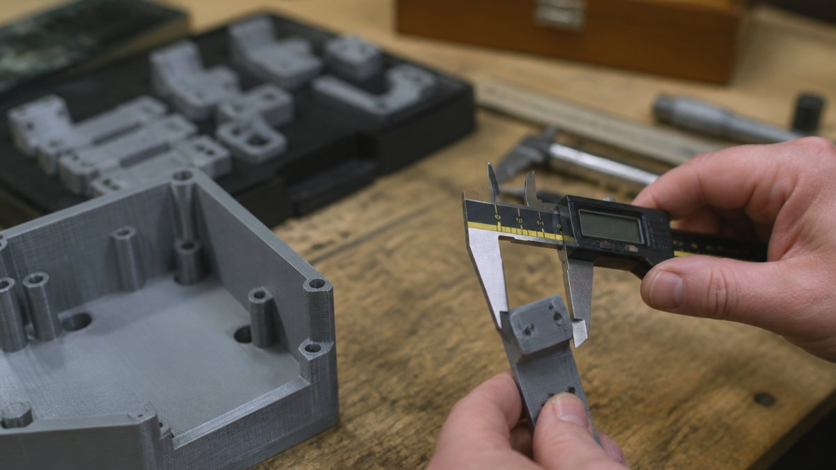
Achieving Tight Tolerances in 3D Printing: A Step-by-Step Guide
Table of Contents
- Understanding 3D Printing Tolerance and Dimensional Accuracy
- FDM vs. Resin Printing Accuracy: Technology Differences
- Factors That Affect Dimensional Accuracy in 3D Printing
- Step 1: Run a 3D Printing Tolerance Test Before Production
- Step 2: Calibrate Your 3D Printer for Accuracy
- Step 3: Design Mating Parts with Proper Clearance and Fit
- Step 4: Apply Dimensional Compensation in CAD or Slicer
- Step 5: Choose Post-Processing When Tightening Tolerances Alone Won't Work
- Troubleshooting Common Tolerance Problems
- Frequently Asked Questions
Last Updated: October 5, 2026
Understanding 3D Printing Tolerance and Dimensional Accuracy
Achieving tight tolerances in 3D printing means controlling how close your final part comes to its designed dimensions, the difference between a prototype that fits together and one that doesn't.
At Alex 3D Print Us LLC, we work with clients who need parts to function, not just look good. A promotional item with loose tolerances might still work; a functional prototype with loose tolerances will fail assembly.
Tolerance is the acceptable range of variation from a target dimension. If you design a hole to be 10 millimeters, tolerance tells you whether 10.05 millimeters or 9.95 millimeters is acceptable. Without tight tolerances, parts won't assemble. With them, your design works as intended.
What Tolerance Means in Additive Manufacturing
In 3D printing, tolerance is harder to control than in traditional manufacturing. Your printer lacks a CNC machine's precision, and material shrinkage, warping, and shifting environmental conditions all affect final dimensions.
The key is understanding what your printer can actually do. Most FDM printers hold ±0.3 to ±0.5 millimeters on standard parts; resin printers achieve ±0.1 to ±0.2 millimeters. These are baselines you can tighten with calibration and design strategy.
Precision vs. Repeatability
These terms sound similar but they mean different things.
Precision is how close a single part comes to its target dimension. If a part designed for 10 millimeters measures 10.02, you have good precision on that part.
Repeatability is whether you get the same result every time. Print the same part five times: if one is 10.02 and another 10.15, your printer is repeatable but not precise.
Achieving tight tolerances in 3D printing requires both. A repeatable but imprecise printer produces consistent failures, and a precise one-off you can't repeat is useless for production.
FDM vs. Resin Printing Accuracy: Technology Differences
FDM and resin printing use completely different processes, and that changes what tolerances you can achieve.
FDM printers extrude melted plastic through a nozzle that cools and solidifies. It's fast and affordable, but the layer-by-layer buildup creates dimensional inconsistency: nozzle diameter, layer height, and extrusion rate all affect final dimensions. FDM typically holds ±0.3 to ±0.5 millimeters.
Resin printers cure liquid resin with light one layer at a time. Resin doesn't cool and shrink like FDM plastic, so it holds ±0.1 to ±0.2 millimeters. The tradeoff is cost and limited material choice.
For achieving tight tolerances in 3D printing, resin is the better choice if budget allows. If you're using FDM, expect to invest more time in calibration and post-processing.
Factors That Affect Dimensional Accuracy in 3D Printing
Multiple variables influence whether your part meets tolerance. Understanding them helps you control the outcome.
Material Shrinkage and Warping
Plastic shrinks as it cools, and the amount depends on the material: PLA shrinks less than ABS, and nylon shrinks more than either. Unaccounted-for shrinkage leaves your final part undersized.
Warping happens when different parts of your print cool at different rates: edges cool faster than the center, which pulls inward, leaving a warped part that doesn't fit.
Warping is worse with large flat surfaces, thicker walls, and high-shrink materials like ABS. Temperature control in your print chamber reduces it, so heated enclosures are a factor in achieving tight tolerances in 3D printing.
Build Orientation and Print Direction
Build orientation affects tolerances: parts are more accurate along the XY plane (horizontal) than along the Z axis (vertical, layer by layer).
Critical dimensions running horizontally achieve tighter tolerance; vertical ones see more variation, since each layer is a separate extrusion event and layer-to-layer variation adds up over height.
Thin walls print more accurately than thick walls. A 1-millimeter wall holds tolerance better than a 5-millimeter wall because there's less material to shrink and warp.
Environmental and Machine Repeatability
Room temperature matters: a shop that swings from 65 to 75 degrees Fahrenheit across the day will produce varying prints. Heated enclosures stabilize temperature and improve repeatability.
Machine calibration drifts over time: nozzles wear, beds warp slightly, belts stretch. These small changes compound into tolerance drift, so a printer accurate three months ago may be off today.
Achieving tight tolerances in 3D printing requires environmental control and regular calibration checks.
Step 1: Run a 3D Printing Tolerance Test Before Production
Before you print your actual part, print a calibration coupon. This is a test piece that measures how your printer performs right now.
Creating and Printing a Calibration Coupon
A calibration coupon is a small part with known dimensions and critical features, typically including:
- Holes of various sizes (8mm, 10mm, 12mm)
- Walls of different thicknesses (1mm, 2mm, 3mm)
- A flat surface for measuring overall shrinkage
- Text or fine details to check surface finish
Print the coupon in the same material, orientation, slicer settings, and environment as your final part.
Measuring Results with Calipers and Micrometers
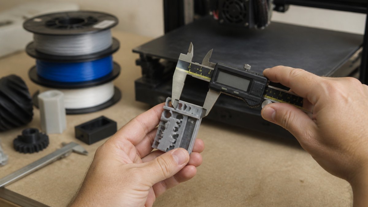
Measure every feature on the coupon. Use digital calipers for general dimensions. Use a micrometer for critical tolerances. Record everything.
Compare measurements to designed dimensions and calculate the deviation: a hole designed at 10 millimeters that measures 10.3 is oversized by 0.3 millimeters, telling you how much to compensate.
Run multiple coupons. Print three or four. Measure them all. If they're all 10.3 millimeters, you have a consistent offset.
You can compensate. If one is 10.1, another is 10.4, and a third is 10.25, you have repeatability problems. Your printer needs calibration before you print production parts.
Step 2: Calibrate Your 3D Printer for Accuracy
Calibration is where you convert a measured error into a corrected print. The goal is not to chase a single perfect coupon, it is to build a repeatable loop: change one variable, print, measure, compare, and only then move to the next variable. Changing two settings at once makes it impossible to know which one moved the dimension.
The Calibration Order of Operations
Work in this sequence. Each step depends on the one before it, and skipping ahead means redoing work.
- Mechanical baseline. Level the bed and set first-layer squish. Confirm belts are tensioned and the gantry moves without binding. A loose belt shows up as oval holes and inconsistent X-versus-Y dimensions, and no slicer setting fixes it.
- E-steps (extruder steps per millimeter). This tells the printer how much filament to push for a commanded length. If E-steps are wrong, every extrusion-based dimension is wrong. Mark 120mm of filament above the extruder inlet, command a 100mm extrude, and measure what is left. Adjust the steps-per-mm value proportionally and repeat until the commanded and actual lengths match.
- Flow rate (extrusion multiplier). Print a single-wall cube with a known wall thickness, measure the wall with calipers, and divide the measured thickness by the slicer's commanded thickness. That ratio is your flow correction. Most printers land between 0.92 and 1.00.
- Dimensional compensation. Only after E-steps and flow are dialed in do you apply XY or shrinkage compensation. Compensating before the extrusion is correct just masks the real error.
Nozzle Height, Line Width, and Layer Height Adjustment
Nozzle height (first-layer Z offset) sets the foundation. Too high and the first layer doesn't bond, so corners lift and the part measures short; too low and the nozzle plows through the layer, causing ridges and inconsistent top surfaces. Tune with a first-layer test patch in 0.01mm increments.
Layer height is the thickness of each printed layer. Keep it between roughly 25 and 75 percent of nozzle diameter, 0.1mm to 0.3mm on a 0.4mm nozzle. Smaller layers (0.1mm to 0.15mm) improve vertical resolution and surface finish but don't fix XY dimensions, which are governed by extrusion width and flow, and they increase print time roughly in proportion to the reduction.
Line width is how wide the extruded strand is, derived by the slicer from nozzle diameter and flow. If external features measure oversized, reduce line width or flow; if undersized, increase flow. Adjust flow first and treat line width as a fine trim.
Upload your STL file for an instant quote →
XY Compensation in Your Slicer Settings
XY compensation (also called horizontal expansion, dimension compensation, or shrinkage compensation depending on the slicer) offsets the part in the horizontal plane before slicing. If your coupon shows every hole is 0.3mm oversized and every outer wall is 0.3mm oversized, a single negative compensation of 0.3mm corrects both.
Two cautions:
- Holes and outer walls do not always move together. If holes are undersized while outer walls are oversized, a single XY value cannot fix both. That pattern usually points to flow being too high, and it should be corrected at the flow stage, not with compensation.
- Do not apply the full error at once. Apply about half the measured deviation, print a fresh coupon, and re-measure. Overshooting compensation creates a new error in the opposite direction and can make the part unusable for a mating feature.
Validating the Calibration
A calibration is only finished when it repeats. Print three coupons back to back with the final settings and measure the same feature on each. If the spread between the smallest and largest measurement is small relative to your target tolerance, the printer is repeatable and the compensation is trustworthy. If the spread is large, stop and fix repeatability before applying any compensation, a compensation value applied to an inconsistent printer just moves the average and leaves the variation intact.
Step 3: Design Mating Parts with Proper Clearance and Fit
Achieving tight tolerances in 3D printing isn't just about individual part accuracy. It's about how parts fit together.
Clearance, Interference Fit, and Tight Fit Definitions
Clearance is intentional space between mating parts, so a hole and shaft don't touch. It's the safest fit for 3D printing because tolerance errors won't lock parts together.
Interference fit means the shaft is slightly larger than the hole, so assembly squeezes them into a tight, permanent bond. It requires tight tolerances; loose ones won't work.
Tight fit (also called normal fit) is the middle ground. Parts fit snugly without being forced. Tight fit requires moderate tolerances.
For 3D printing, start with clearance fits. They're more forgiving. Once you understand your printer's capabilities, move to tight fits if needed.
Recommended Gaps for Assembled Parts
For FDM printing with ±0.3mm tolerance, use these guidelines:
- Clearance fit: Add 0.5mm to 1mm gap between parts
- Tight fit: Add 0.1mm to 0.3mm gap
- Interference fit: Subtract 0.1mm to 0.3mm (shaft smaller than hole)
These are starting points. Print test assemblies and fit the parts: if too loose, reduce the gap; if too tight, increase it.
For resin printing with ±0.1mm tolerance, you can use tighter gaps:
- Clearance fit: 0.2mm to 0.5mm
- Tight fit: 0.05mm to 0.15mm
Step 4: Apply Dimensional Compensation in CAD or Slicer
Once you know how your printer behaves, compensate before printing.
You have two options: adjust in CAD or adjust in the slicer.
CAD adjustment means editing your design file, scaling the part or specific features for shrinkage. It's permanent, so every print uses the compensated design.
Slicer adjustment applies compensation in your slicing software. Most slicers have a scaling or compensation feature, letting you shrink or expand the design without changing the CAD file.
For production runs, CAD adjustment is cleaner. For prototyping and testing, slicer adjustment is faster.
Don't apply compensation blindly, base it on your calibration coupon results. If features are 0.2mm undersized, compensate by +0.2mm, print another test, measure, and refine.
Step 5: Choose Post-Processing When Tightening Tolerances Alone Won't Work
Sometimes print settings alone won't achieve your tolerance. Post-processing fills the gap.
Common post-processing for tight tolerances includes:
- Sanding: Smooth surfaces and reduce dimensions slightly
- Reaming: Enlarge holes to exact size with a reaming tool
- Tapping: Add threads to holes
- Polishing: Improve surface finish, which affects fit
- Vapor smoothing: Use chemical vapor to smooth FDM parts (changes dimensions)
Post-processing takes time and cost, so use it when the tolerance gap is small (under 0.2mm) and printer calibration alone can't close it.
For tight tolerance requirements, plan post-processing into your timeline and budget.
Troubleshooting Common Tolerance Problems
Most tolerance guides stop at "check your bed leveling." The harder problem is separating a real dimensional error from a measurement error, then knowing whether it's consistent (correctable with compensation) or random (a machine or environment problem).
Measure Before You Diagnose: Metrology Basics
A reported tolerance is only as good as the measurement behind it. Before blaming the printer, rule out the measurement.
- Tool choice. Digital calipers suit general dimensions but resolve to about 0.01mm and are easy to tilt or squeeze. Use a micrometer for critical features, and a pin gauge or bore gauge for holes, calipers measure a chord unless held perfectly square.
- Measurement location. A single caliper reading is not a dimension. Measure the same feature at three or more points and record the range, a wall reading 2.00mm on one side and 2.12mm on the other hides a 0.12mm variation from a single reading.
- Operator technique. Over-tightening calipers compresses soft plastic and reads small, so consistent, light contact matters more than resolution. Have the same person measure the same way across coupons.
- Temperature. Plastic and metal change dimension with temperature. Let parts cool to room temperature and measure coupons and production parts under the same conditions.
Symptom-to-Cause Diagnostic Table
Use this to map what you observe to the most likely cause, then fix in order.
| Symptom | Likely cause | First corrective action |
|---|---|---|
| All holes undersized, outer walls oversized | Flow too high | Reduce flow rate, reprint coupon |
| All dimensions uniformly off by the same amount | Consistent offset | Apply XY compensation at half the error |
| X and Y dimensions differ from each other | Belt tension, gantry binding, or E-steps | Check belts and mechanical motion first |
| Z dimensions off but XY is fine | Layer height, first-layer squish, or Z steps | Verify Z calibration and first-layer offset |
| Dimensions vary print to print | Repeatability problem | Check temperature stability, material batch, nozzle wear |
| Part warps or lifts at corners | Thermal shrinkage, poor bed adhesion | Enclosure, brim, or higher bed temperature |
| Holes oval rather than round | Belt tension or backlash | Tension belts, check for play in the motion system |
Holes Undersizing or Features Oversizing
Holes undersizing is the most common FDM complaint: the extruded strand is slightly wider than the slicer's nominal width, so small holes close in. Oversized external walls are the same root cause, too much material.
Fix in this order:
- Reduce flow rate by 2 to 3 percent and reprint the coupon.
- If holes are still undersized but walls are correct, apply a small negative hole compensation if your slicer supports it separately.
- Check the nozzle for wear. A worn nozzle extrudes a wider, less controlled bead and throws off every dimension.
- Only then apply negative XY compensation as a final trim.
Inconsistent Results Across Multiple Prints
Your first print is perfect, the second is 0.4mm off, the third different again. This is a repeatability failure, the hardest tolerance problem, because compensation only shifts the average and cannot fix variation.
Work through these in order:
- Bed leveling and first-layer consistency. A bed that's level in one corner and low in another produces parts that differ depending on where they sit on the plate.
- Temperature stability. Bed and ambient room temperature swings change shrinkage. Log room temperature across a print run; a swing of more than a few degrees can explain the variation.
- Material batch. Filament diameter and formulation vary between spools and batches. Measure diameter at several points and test with a fresh, measured spool.
- Nozzle condition. A partially clogged or worn nozzle extrudes inconsistently. Replace and re-test.
- Mechanical wear. Belts stretch, bearings loosen, lead screws collect debris, showing up as gradual drift over weeks, not sudden jumps.
Tolerance Stack-Up in Multi-Part Assemblies
Individual parts can each pass their tolerance and the assembly still fail. That's stack-up: each part's variation adds to the others'.
Three parts varying ±0.2mm that stack in the same direction can put the assembly off by ±0.6mm. Allocate a tolerance budget before you print, not after assembly fails.
A practical approach:
- Decide the assembly's total allowable variation first.
- Divide that budget across the parts, giving tighter tolerances to the parts that are easiest to control.
- Design clearance into the assembly so that worst-case stack-up still fits.
- Where stack-up is unavoidable, designate one part as the adjustment feature, a hole you ream or a face you sand to final size after assembly.
Frequently Asked Questions
How much tolerance should I allow for a tight fit in 3D printing?
Tight fit tolerances in 3D printing typically range from 0.2 to 0.5 mm depending on your technology and material. FDM printers generally require larger clearances (0.3-0.5 mm) due to extrusion variability, while resin printers can achieve tighter fits (0.2-0.3 mm). Always run a tolerance test on your specific printer and material before designing for tight fits, as dimensional variation differs by machine, nozzle diameter, and layer height.
How do you improve dimensional accuracy in 3D printing?
Start by calibrating your printer: verify nozzle height, adjust line width and layer height in your slicer, and apply XY compensation if your prints consistently oversized or undersized. Run a tolerance test to measure actual deviation from nominal dimensions. Then compensate in your CAD model or slicer settings based on measured results. Material choice and build orientation also affect accuracy, print test parts in different orientations to identify the best direction for your feature.
What is the difference between FDM and resin printing accuracy?
FDM (Fused Deposition Modeling) typically achieves ±0.3-0.5 mm accuracy due to extrusion variability and layer-by-layer deposition. Resin printing (SLA/LCD) offers better dimensional accuracy, around ±0.1-0.2 mm, because liquid resin solidifies more uniformly. However, resin parts are prone to shrinkage during post-curing, which can shift tolerances.
Should I print a tolerance test before making a functional part?
Yes, always print a tolerance test coupon before production. A test coupon includes holes, bosses, and features at your target dimensions so you can measure actual deviation with calipers or a micrometer. This reveals how your printer, material, and slicer settings perform in practice. Results guide your calibration adjustments and compensation strategy, saving time and material on failed functional parts. A single test print typically takes 30-60 minutes and prevents expensive mistakes.