
How to Prepare STL Files for 3D Printing
Table of Contents
- What You'll Need Before Starting
- STL File Export Settings for 3D Printing
- Checking Your Mesh for Errors
- How to Fix Non-Manifold Geometry
- Scaling and Resizing Your Model
- Best STL Repair Software and Tools
- Optimizing File Size and Polygon Count
- Orientation and Support Structure Planning
- Final Quality Check Before Printing
- Common Mistakes to Avoid
- Frequently Asked Questions
Last Updated: October 1, 2026
What You'll Need Before Starting
Preparing STL files for 3D printing requires CAD software, a file viewer, and mesh repair tools, but not expensive ones. Most importantly, understand what makes an STL file print-ready: it's not just exporting and hoping for the best.
The core requirement is a valid STL file: a 3D model represented as a mesh of triangular polygons. Before exporting, confirm your model is watertight and error-free. This single step prevents most printing failures.
Know your printer's capabilities: different materials (PLA, PETG, ABS, TPU) have different tolerance and accuracy requirements. Understanding your target printer's specifications before preparation saves revision cycles.
STL File Export Settings for 3D Printing
How to prepare STL files for 3D printing begins with correct export settings. Many designers export with defaults and fail. The export dialog holds critical parameters that determine print success.
Control mesh resolution via tessellation or deviation settings. Lower deviation preserves detail but increases file size; higher deviation reduces polygons but may lose features. Use 0.1-0.5 mm deviation for functional parts, 0.05 mm for detailed cosmetic parts.
Enable surface smoothing or normal averaging to reduce faceting on curved surfaces. Verify your CAD model's unit scale before export, exporting inches as millimeters creates parts 25x the wrong size.
Use binary STL format, it's smaller and faster than ASCII, and prevents corruption during file transfer.
Checking Your Mesh for Errors
A mesh is print-ready only if manifold: every edge shared by exactly two triangles, forming a closed, watertight volume. Non-manifold geometry causes slicer failure. Check before printing to save time and material.
Open your STL in Meshmixer or Fusion 360's viewer to highlight problems. Look for red indicators showing non-manifold edges, holes, or intersecting geometry. Even one small hole renders a file unprintable.
Common mesh errors include:
- Open edges where triangles don't connect properly
- Inverted normals (triangles facing the wrong direction)
- Self-intersecting geometry
- Duplicate vertices or degenerate triangles (triangles with zero area)
Use automated error detection for complex models. Most tools offer one-click fixes for simple problems, but verify results before printing. Serious issues may require returning to CAD and re-exporting.
How to Fix Non-Manifold Geometry
Non-manifold geometry violates the rules of a closed, solid surface. Fix it via automated repair or manual correction, depending on severity. Not all tools handle complex repairs equally.
Automated repair fixes simple issues: small holes, inverted normals, duplicate vertices. Use Meshmixer's "Analysis" and "Auto Repair" features. Verify results by re-analyzing the mesh after repair.
For complex non-manifold geometry, identify the problem area and either delete and rebuild in CAD, use mesh editing tools to close holes, or re-export with different settings. If walls are thinner than your printer's minimum (typically 0.8-1.5 mm), thicken them and re-export.
The key is understanding that manifold geometry is non-negotiable for 3D printing. A file that's "almost manifold" will fail. Either fix it completely or return to CAD and redesign.
Scaling and Resizing Your Model
How to prepare STL files for 3D printing includes getting dimensions exactly right, small errors compound during printing. Most scaling errors stem from forgetting to verify units.
Confirm the STL file's current dimensions in a viewer or slicer. If the bounding box shows wrong units (e.g., 250 units instead of 250 mm), fix the unit scale before printing.
Maintain aspect ratios when scaling unless distorting intentionally. Use uniform scaling for most parts; non-uniform scaling adjusts specific dimensions like press-fit hole diameter.
Consider your printer's build platform size. Scale down 5-10% to ensure the part fits comfortably and accounts for platform offset errors.
After scaling, re-check mesh integrity. Scaling can introduce floating-point errors. Re-run error detection to confirm the file is still manifold.
Best STL Repair Software and Tools
Several tools excel at mesh repair and STL preparation. Choosing the right one depends on your workflow, budget, and the complexity of your models. Free tools handle most common issues, but professional software offers advanced features for complex geometry.
Meshmixer (free, Autodesk) is the industry standard for mesh repair. It's intuitive, handles complex geometry well, and includes analysis tools to identify errors. The learning curve is minimal for basic repairs. For most designers, Meshmixer solves 90% of mesh problems without leaving the tool.
Fusion 360 (free with limitations, Autodesk) includes native mesh repair within its CAD environment. If you're already using Fusion for design, repair directly in the same software. This eliminates file transfer steps and keeps your workflow simplified.
Netfabb (paid, Autodesk) is the professional option. It handles extremely complex geometries, includes advanced support structure generation, and offers batch processing for multiple files. If you're preparing dozens of files, Netfabb's automation saves hours.
FreeCAD (free, open-source) includes mesh workbench tools for inspection and basic repair. It's less specialized than Meshmixer but sufficient for simple fixes and a good option if you want everything in one application.
For how to fix non-manifold geometry specifically, Meshmixer's manual editing tools and automated repair are most effective. The software shows you exactly where problems exist and walks you through fixes step-by-step.
Optimizing File Size and Polygon Count
Large STL files slow down slicing, consume excessive memory, and may crash older software or web-based tools. File size optimization through mesh decimation removes unnecessary polygons without sacrificing print quality. However, aggressive decimation can destroy fine features, so the process requires a systematic approach and validation.
STL files store geometry as triangular polygons. A typical file contains 50,000 to 5 million polygons. File size scales with polygon count: 1 million polygons ≈ 30-50 MB; 5 million ≈ 150-250 MB. Beyond 100 MB, slicers become sluggish. However, a 5 million polygon part prints nearly identically to a 500,000 polygon version. Extra polygons add file size without improving quality, this is where decimation helps.
Mesh decimation reduces polygon count by merging vertices and removing redundant triangles while preserving sharp edges. Target polygon counts: small functional parts (under 50 mm) 50,000-200,000; medium parts (50-200 mm) 200,000-500,000; large parts (over 200 mm) 500,000-1,000,000; highly detailed cosmetic parts 1,000,000-2,000,000; complex assemblies 100,000-300,000 per part.
Test decimation iteratively: (1) Note original polygon count and file size. (2) Reduce by 20-30% and check for loss of sharp edges, fine features, or dimensional changes. (3) Validate in your slicer, compare layer preview with the original. (4) Repeat if acceptable, stopping when quality noticeably degrades. (5) Test print if critical.
Meshmixer (free): Use "Modify" → "Reduce" with a 50% reduction target. Netfabb (paid): Better for complex geometry with edge preservation. Fusion 360 (free): Use "Modify" → "Simplify Mesh." CloudCompare (free): More technical but powerful for complex geometry. Cura (free): "Mesh Fixes" plugin decimates during slicing, but pre-slicing decimation gives more control.
Avoid decimating: parts with fine text/logos (under 2 mm), assemblies with tight tolerances, parts with thin walls (under 1 mm), and organic shapes with complex curvature.
File size depends on export resolution. Before decimating, try re-exporting with coarser deviation: 0.1-0.2 mm is the sweet spot for most parts. Re-exporting is often faster and produces better results than decimating a finely-exported file.
For multi-part assemblies, decimate each part individually to 200,000-500,000 polygons, then re-import and verify fit and support placement.
After decimation, verify: file size under 100 MB, polygon count in target range, no obvious detail loss, slicer preview matches original, critical dimensions unchanged, mesh still manifold, supports placed identically, and test print (if available) matches expectations.
Orientation and Support Structure Planning
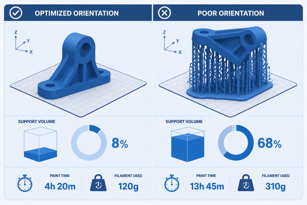
Part orientation is one of the highest-impact decisions in STL preparation. Poor orientation can double print time, waste 30-50% of material on supports, and create weak points. Orientation decisions require understanding your printer's capabilities and your part's functional requirements.
FDM printers build layer-by-layer in the Z-axis, creating weakness when stress runs parallel to layers. A vertically oriented part may be 50% weaker than the same part horizontal. Support material is the second factor: a poorly oriented part might need 40% support; rotated correctly, only 5%.
Upload your STL file for an instant quote →
Identify stress directions and orient perpendicular to layers. Analyze overhangs (surfaces angled over 45° from vertical) and rotate to minimize them. Use your slicer's preview to visualize support placement before committing.
For multi-part assemblies, orientation becomes more complex. If you're printing an assembly with moving pieces, consider whether parts should be printed separately and assembled, or printed in-place. Print-in-place designs (parts that move without assembly) require precise orientation to ensure supports don't jam the mechanism. Separate parts offer more flexibility in orientation but require assembly labor.
Testing Orientations in Your Slicer
Most slicers (Cura, PrusaSlicer, Bambu Studio) allow you to rotate parts and preview support structures in real-time. Load your STL file and test at least three different orientations:
- Default orientation (as exported from CAD)
- Rotated 90 degrees on the longest axis
- Rotated to minimize support volume (rotate until the slicer shows the least support material)
For each orientation, note:
- Total support volume (usually shown in grams or cubic centimeters)
- Estimated print time
- Whether critical surfaces have supports touching them
- Layer line direction relative to stress points
The optimal orientation is rarely obvious. A part that looks best in CAD might print fastest in a completely different orientation. Always test in your slicer before uploading.
Tolerance and Clearance Considerations
Orientation also affects dimensional accuracy. Most FDM printers have tighter tolerances in the XY plane (horizontal) than in the Z-axis (vertical). If your part has critical dimensions, orient it so those dimensions run horizontally rather than vertically. For example, a hole that must be 10 mm diameter should be oriented so the hole axis is horizontal, not vertical.
For assemblies with press-fits or moving parts, add clearance based on your printer's accuracy. Most consumer FDM printers have ±0.3 mm accuracy; professional machines achieve ±0.1 mm. If two parts must fit together, add 0.5-1 mm clearance between them. Orientation affects how this clearance distributes: a vertical press-fit is more forgiving than a horizontal one because gravity helps parts seat.
Multi-Color and Multi-Material Printing
If you're using a multi-material printer (like Bambu Lab X1 Carbon with AMS), orientation affects color transitions. Most multi-material prints use layer-by-layer color changes. If you want a color boundary to align with a specific feature (like a logo or text), orient the part so that feature aligns with the layer direction. This minimizes visible transitions and reduces the number of filament swaps needed.
Common Orientation Mistakes
- Printing with the default orientation without checking support volume. Always rotate and compare.
- Orienting for aesthetics instead of function. A part that looks good in CAD might print poorly. Function comes first.
- Ignoring layer line direction for stress-bearing parts. This is the #1 cause of unexpected failures in functional prints.
- Over-rotating to avoid all supports. Sometimes a small amount of support material is worth it to improve print quality or reduce print time.
- Forgetting to account for build platform offset. Some printers have a slight offset on the platform. Orient parts with a small margin from the platform edges.
Final Orientation Checklist
Before exporting your STL for printing:
- Identify primary stress direction and orient perpendicular to layers
- Test at least three orientations in your slicer
- Compare support volume, print time, and surface quality for each
- Verify critical dimensions are oriented for best accuracy
- Check that no supports contact critical surfaces
- For assemblies, confirm parts will fit after accounting for print tolerances
- Preview the final print in your slicer and rotate one more time if needed
Orientation is not a one-time decision. If your first print fails or prints poorly, the second thing to try (after checking mesh integrity) is rotating the part. Many print failures are actually orientation failures, not design flaws.
Final Quality Check Before Printing
Before uploading your STL file to a 3D printing service, perform a final quality check. This step catches problems that would otherwise result in failed prints and wasted time.
Verify dimensions one last time. Measure critical features in your CAD model and confirm the STL file shows the same dimensions. Use your slicer to check bounding box size. If anything seems off, return to CAD and re-export.
Check for manifold geometry using your slicer's analysis tools. Most slicers highlight non-manifold edges or holes in red. If you see any red, don't print, fix the mesh first.
Inspect the mesh visually. Rotate the model in your viewer and look for obvious defects: holes, spikes, or degenerate geometry. If something looks wrong in the viewer, it will fail during printing.
Verify material compatibility. Confirm your STL file is compatible with your chosen material. Some designs work in PLA but fail in PETG due to thermal stress. Check wall thickness, feature size, and overall geometry against your material's requirements.
Review support structure placement. If your slicer generated supports, check that they're positioned where they won't damage critical surfaces. Adjust orientation or support settings if needed.
Test print a small version if possible. For complex parts, printing a scaled-down test version catches problems before committing to a full-size print.
Common Mistakes to Avoid
Most STL preparation mistakes fall into predictable categories. Avoiding these saves time, material, and frustration.
Exporting with default settings is the most common error. Default tessellation settings often create meshes with too many or too few polygons. Spend 30 seconds adjusting export parameters before clicking export.
Ignoring unit scale causes parts that are wildly oversized or undersized. Always verify your CAD model's unit system matches your intended print size. If your model is in inches but you need millimeters, scale it 25x before exporting.
Skipping mesh inspection means problems aren't caught until slicing fails or printing produces garbage. Always open your STL file in a viewer after export. This takes two minutes and prevents hours of troubleshooting.
Designing with features too small to print wastes material and time. Most 3D printers can't print details smaller than 0.5 millimeters. Walls thinner than 0.8 millimeters fail frequently. Design with your printer's capabilities in mind.
Poor part orientation leads to excessive support material and weak parts. Don't just hit "print" with the default orientation. Rotate your part to minimize supports and align stress with layer direction.
Over-optimizing file size removes detail you actually need. Decimation is useful, but aggressive reduction can destroy fine features. Test your decimation results before printing.
Forgetting tolerance and clearance causes assemblies to jam or parts to fall apart. If your design has moving pieces or press-fits, add clearance for 3D printing tolerances. Most 3D printers have ±0.3 millimeter accuracy.
Preparing STL files for 3D printing requires attention to detail at every step, from export settings to final mesh validation. The process seems complex, but each step prevents specific, predictable failures. Master these fundamentals, and your prints will succeed consistently.
When you're ready to print, upload your optimized STL file to Alex 3D Print Us LLC for an instant quote. Our team handles complex geometries, multi-color printing with Bambu Lab technology, and tight tolerances. Whether you need functional prototypes, promotional items for trade shows, or custom branded merchandise, we deliver precision results with fast turnaround times. Get started today and see why businesses trust us with their most demanding fabrication projects.
Frequently Asked Questions
What is the best software to prepare STL files for 3D printing?
Popular options include Fusion 360 (free for personal use), FreeCAD, Meshmixer, and Netfabb for repair and inspection. Your choice depends on your workflow: CAD software like Fusion 360 handles export and basic scaling, while specialized repair tools excel at fixing non-manifold geometry and mesh errors. Most professionals use a combination of tools. For quick checks, many slicers include built-in file analysis. Test a few free options to see which fits your design process best.
How do I check if my STL file is manifold and watertight?
A manifold STL has no gaps, holes, or non-manifold edges, critical for successful printing. Open your file in Netfabb, Meshmixer, or your slicer software. These tools highlight errors in red or flag non-manifold vertices. Look for the 'Analyze' or 'Check Geometry' function. If your file shows errors, the software typically offers auto-repair options. You can also slice your file in PrusaSlicer or Bambu Studio, they'll warn you if the mesh has issues before you print.
What are the best export settings for STL files from CAD software?
Export as ASCII or Binary STL (Binary is smaller). Set your tolerance to 0.01-0.05 mm depending on detail level, tighter tolerances create larger files but capture finer geometry. In Fusion 360, use 'File > Export' and choose STL format with Medium or Fine mesh density. Check that your model is a solid body, not a surface. Always verify dimensions before export: confirm your model is scaled correctly in the CAD software. Export at the exact size you intend to print to avoid scaling errors later.
Can I use AI tools to generate or fix STL files?
AI can generate basic STL files from text descriptions or images, but results often require manual repair. Tools like ChatGPT cannot directly create print-ready files, you'll need to export their output and check for manifold geometry. For fixing existing files, AI-assisted tools are emerging, but traditional repair software like Netfabb remains more reliable. AI works best for concept generation; always validate the mesh geometry and test print a small prototype before committing to a full production run.