
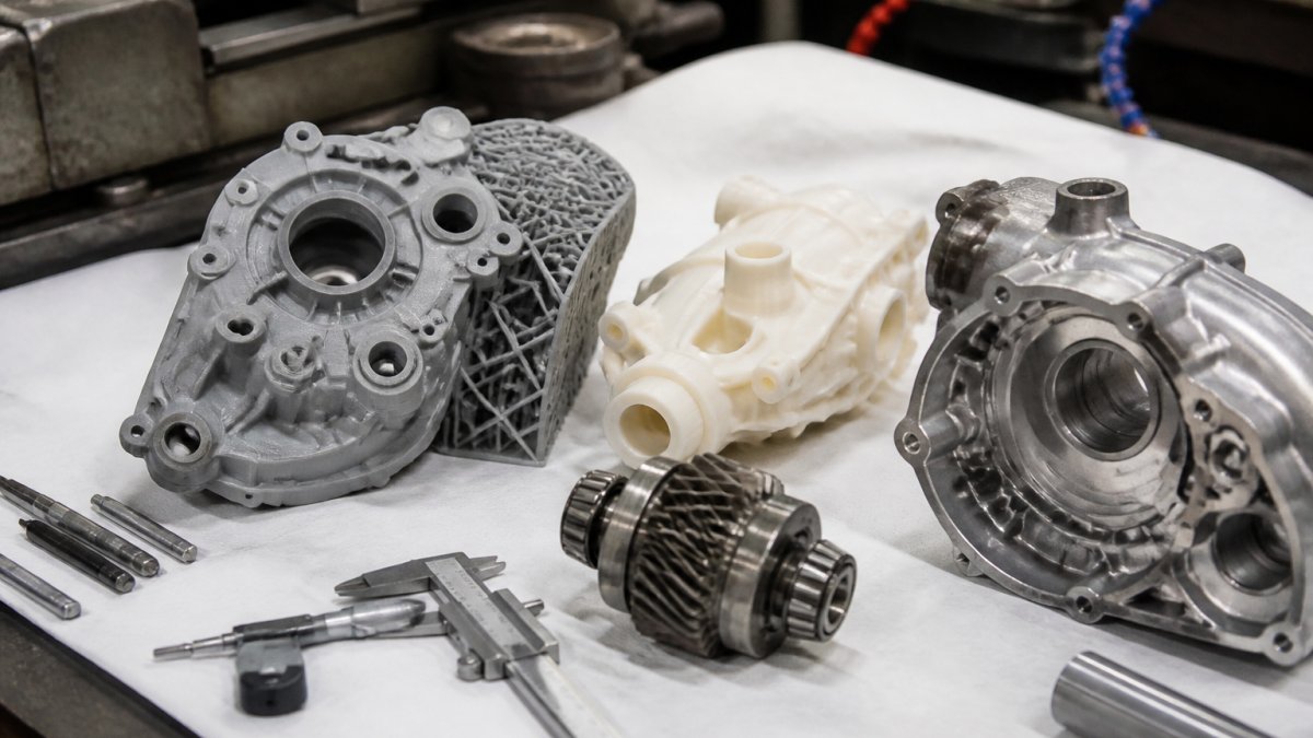
How to Prototype Complex Mechanical Parts
Table of Contents
- Understanding the Mechanical Prototyping Process
- Moving from CAD Design to a Functional Prototype
- Choosing Between 3D Printing and CNC Machining
- Selecting Mechanical Prototype Materials for Performance
- Testing and Validating Your Mechanical Prototype
- Iterating Quickly: Design Changes and Turnaround Time
- Managing Cost and Lead Time for Complex Assemblies
- Frequently Asked Questions
Last Updated: October 12, 2026
Understanding the Mechanical Prototyping Process
To prototype complex mechanical parts requires a structured approach that bridges design intent and physical reality.
The process starts with a clear design goal: validating fit, testing material performance under load, or verifying a complex assembly works. Each goal demands a different strategy.
Most teams skip this step and jump straight to manufacturing, where budget disappears and timelines slip. A rough prototype might reveal an impossible tolerance stack-up, gears that bind under load, or an assembly that needs a third hand. Catching these issues in prototyping costs hundreds; in production, thousands.
The path forward involves four decisions: choosing rapid prototyping methods, selecting materials that match performance requirements, building and testing, then iterating on what you learn.
Moving from CAD Design to a Functional Prototype
Your CAD model is a promise, not a guarantee. The jump from digital to physical reveals hidden assumptions.
Before sending anything to manufacturing, validate your CAD design against real-world constraints: features too small to manufacture reliably, physically impossible assembly sequences, and a tolerance stack-up that actually closes.
Validating Your CAD Model Before Manufacturing
A functional prototype from CAD starts with honest design review: Can these parts be made? Can they be assembled in the planned sequence? Will tolerances stack up, or will the assembly be loose or impossible to fit?
Common CAD errors include walls too thin for the process, features smaller than it can reliably produce, and assembly sequences that fail with physical hands. Designs that look perfect on screen often hide these flaws.
Check your design against your chosen method: for 3D printing, verify unsupported overhangs won't sag; for CNC, confirm the tool reaches every feature without collision; for supplier-sourced custom parts, verify lead times fit your schedule.
The best validation is a conversation with the person making your prototype. They spot issues your CAD review missed because they think in toolpaths and support structures, not just geometry.
Choosing Between 3D Printing and CNC Machining
The choice between 3D printing and CNC machining depends on what you're testing and how fast you need answers. "3D printing is fast, CNC is accurate" isn't useful for a complex assembly with mixed requirements. Use a decision framework instead.
A Decision Framework for Complex Parts
Score your prototype against five criteria, then pick the process that wins on the ones that matter most:
- Strength and stiffness, If the part carries structural load or must resist deflection, machined aluminum (6061-T6) or steel behaves like production. Printed plastics (PLA, PETG, standard resin) will flex and creep under sustained load.
- Dimensional accuracy, CNC holds roughly ±0.001 in. to ±0.005 in. on metals depending on setup and feature. FDM printing typically holds ±0.005 in. to ±0.015 in.; SLA/DLP resin can reach ±0.002 in. to ±0.005 in. on small features but drifts on large parts.
- Surface finish, Machined surfaces come off the tool at roughly 63-125 µin Ra; printed parts show layer lines unless post-processed.
- Cost per part, Printing wins at quantity one. CNC setup (fixturing, toolpaths, first-article checks) dominates the cost of a single unit, so machining only becomes economical when you amortize setup across several parts.
- Lead time, Printing a small bracket can be same-day or overnight. Machining a multi-setup part is typically days, longer if material is not on the shelf.
Design-for-Manufacturing Limits to Respect
Before you commit, check your geometry against the process limits. These are the rules that decide whether your design is manufacturable at all:
- 3D printing (FDM): Minimum wall around 0.8-1.2 mm; unsupported overhangs beyond roughly 45° need supports; small holes print undersized and may need drilling; internal channels are easy but trapped support material is hard to remove.
- 3D printing (SLA/DLP): Minimum wall around 0.4-0.6 mm; fine features and small holes are strong suits; large flat surfaces can warp; drainage and cure paths matter for hollow parts.
- CNC machining: Minimum internal corner radius equals the tool radius (a 1/8 in. end mill cannot cut a sharp inside corner); deep pockets need long tools that deflect; undercuts require special tooling or a second setup; thin walls chatter.
If your design violates these limits, fix the CAD before you quote, not after.
The Hybrid Workflow Most Teams Settle Into
Print a rough prototype to validate fit, assembly sequence, and gross function. Once the design is locked, machine functional prototypes from production-intent materials. This catches design errors cheaply and early, then validates performance with parts that behave like production.
NIST engineering metrology references for tolerance and accuracy context
Selecting Mechanical Prototype Materials for Performance
Material choice determines whether your prototype tests what you need to know.
For fit and assembly, material matters less, even a plastic 3D printed prototype shows whether parts collide or the assembly sequence works. For mechanical performance, material is critical: a plastic prototype won't tell you whether your design handles production loads or temperatures.
Match your material to what you're testing: for stress and deflection, use properties close to production; for thermal performance, match conductivity and expansion; for finish or appearance, match the final material as closely as timeline and budget allow.
Common prototype materials include:
- Aluminum and steel for high-strength testing and dimensional accuracy
- High-performance plastics (nylon, PEEK, polycarbonate) for load-bearing testing with faster turnaround
- Standard 3D printing resins and filaments for fit and assembly validation
- Elastomers and rubbers for flexible components and sealing surfaces
The material should answer the question your prototype is designed to answer. A fit prototype can use cheap plastic; a performance prototype needs to match production intent within your timeline and budget.
Testing and Validating Your Mechanical Prototype
A prototype that hasn't been tested is just an expensive toy. Testing reveals whether your design works, and for complex assemblies, failures almost always happen at interfaces, not mid-part.
Start with Assembly and Fit
Start simple: does it assemble in the planned sequence? Do parts fit as intended? Does the mechanism move smoothly or bind? These quick functional tests reveal obvious flaws before you invest in performance testing.
Upload your STL file for an instant quote →
Tolerance Stack-Up and Assembly Validation
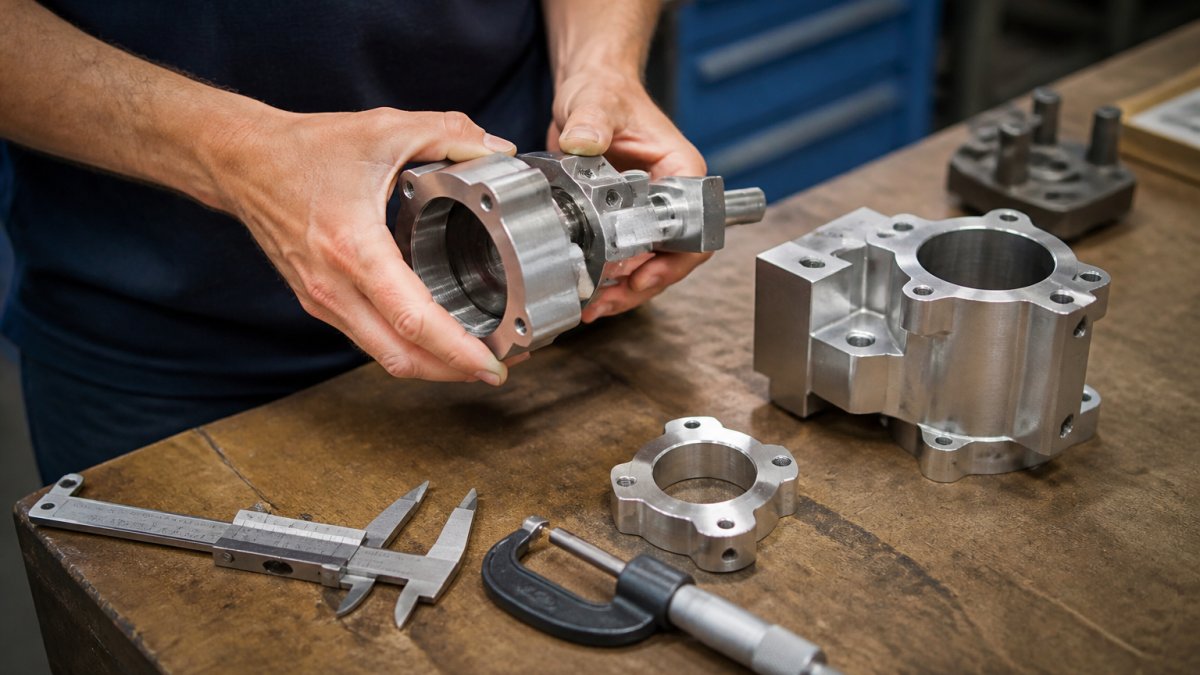
Tolerance stack-up surprises teams building their first prototype of complex mechanical parts. Each part has a tolerance range, and stacking ten parts adds them up. A design that looks fine at nominal dimensions may be impossible to assemble at worst-case extremes.
Two methods are standard:
- Worst-case stack-up, Add every tolerance in the chain at its extreme. This is conservative and guarantees assembly, but often forces tighter (more expensive) tolerances than necessary.
- Statistical (RSS) stack-up, Root-sum-square the tolerances assuming independent, roughly normal distributions. This is realistic for high-volume production but risky for a one-off prototype where you cannot rely on averaging.
For a prototype, calculate worst-case first. If it closes, you're safe. If it doesn't, decide whether to tighten a tolerance, add a shim or adjustment feature, or redesign the interface. Then verify with the physical prototype: measure the actual gap or interference with calipers or a height gauge, and record the number.
That measurement becomes the input to your next iteration.
Performance and Failure Testing
Once basic function checks out, move to performance testing: load test if the part carries load, thermal test if temperature matters, cycle test if it moves repeatedly. Measure deflection, stress, wear, and failure modes, and compare to your analysis.
A practical failure-testing checklist for complex assemblies:
- Static load, Apply the expected load plus a safety margin and watch for yielding, cracking, or fastener pull-out.
- Fatigue/cycle, Run the mechanism through its motion repeatedly and inspect for wear, galling, or loosening.
- Thermal, Heat and cool the assembly to expected extremes and check for binding from differential expansion.
- Wear at interfaces, Inspect bearing surfaces, gear teeth, and sliding contacts after cycling.
- Fastener retention, Confirm screws and press fits stay put under vibration.
- Failure mode, When something breaks, identify whether it failed safely or in a way that would be dangerous in the field.
Identifying Design Changes and Tolerance Issues
Testing reveals where design assumptions were wrong: parts that should fit smoothly bind from a too-tight stack-up, parts that should be rigid flex more than expected, gears make unexpected noise, or assemblies need unrealistic force.
Document every issue: measure the actual gap or interference, test assembly force, and identify the tolerance or feature causing it. This data drives your next iteration.
Iterating Quickly: Design Changes and Turnaround Time
Prototyping is iteration: learn from each version, change, and test again. Speed matters because each cycle costs time and money.
Rapid prototyping compresses this cycle. Printing a new iteration overnight beats waiting a week for machined parts; testing a change the next morning means faster iteration and more learning in the same calendar time.
But speed isn't free: fast methods often use materials or processes that don't match production intent. A 3D printed prototype might reveal an impossible assembly sequence, but not whether your design survives production stresses.
The winning strategy: iterate fast on design and fit, then carefully on performance. Print five iterations to lock down the mechanical design, then machine two from production-intent materials to validate performance. This compresses your timeline while answering the hard questions.
Track what changes between iterations and document what each test taught you. This design history helps you avoid repeating mistakes and understand which choices actually matter.
Managing Cost and Lead Time for Complex Assemblies
Complex assemblies multiply costs and timelines: every component adds manufacturing time and coordination delays.
A single machined part might take three days; a ten-part assembly might take two weeks, since each part has its own lead time and you can't assemble until all arrive.
Plan your supply chain early: order long-lead parts first, identify critical-path parts whose delay stalls the whole assembly, and build buffer time for the parts that always slip.
Consider simplifying your design: fewer parts means fewer lead times, lower assembly labor, and fewer failure points. Sometimes two complex parts beat ten simple ones.
For complex assemblies, communicate your timeline to your manufacturing partner. They can identify bottlenecks and suggest design changes that reduce lead time.
Get an instant quote by uploading your STL file.
Prototyping complex mechanical parts is a discipline of learning fast and testing smart: start with clear questions, choose methods that match your goals, test thoroughly, document what you learn, and iterate.
Frequently Asked Questions
How do you make a functional prototype from a CAD model?
Start by validating your CAD design for manufacturability, then choose your manufacturing method based on part complexity and material needs. Export your design as an STL file, select either 3D printing for rapid iteration or CNC machining for tight tolerances, and work with your fabrication partner to build the first sample. Test the assembled prototype for fit, function, and performance, then use results to refine your design before the next iteration.
What's the best mechanical prototyping process for complex assemblies?
Break complex assemblies into phases: design individual components in CAD, prototype each part separately using the appropriate method (3D printing for complex geometry, CNC for wear-resistant parts), then assemble and test the full unit. Validate tolerances at each assembly stage to catch stack-up issues early. This modular approach reduces cost and turnaround time while letting you iterate on problem areas without rebuilding entire assemblies.
Which materials are best for mechanical prototypes?
Material choice depends on the part's function. High-performance plastics like ABS and nylon work well for custom parts with complex geometry and moderate loads. Aluminum and steel are better for functional prototypes needing wear resistance or tight tolerances. For rapid prototyping, resin-based materials offer fine detail and faster turnaround. Discuss material performance requirements with your fabrication partner to balance durability, cost, and production speed.
Can 3D printing actually be used for functional mechanical parts?
Yes, 3D printing works for functional prototypes when material selection matches the part's performance needs. Additive manufacturing excels at producing complex geometries, custom components, and intricate parts that would be expensive to machine. However, 3D printed parts may need post-processing or assembly with standard machine elements like gears, pulleys, and sprockets to handle higher loads. For parts requiring extreme wear resistance or high precision, CNC machining is often the better choice.