
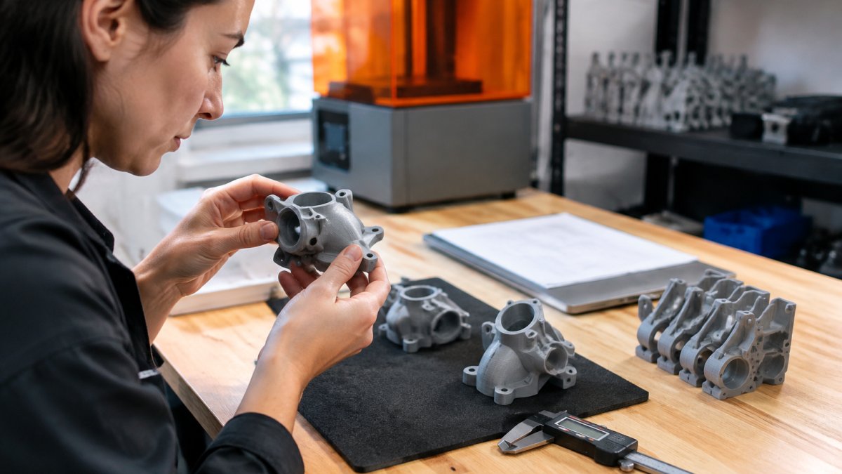
3D Printing Quality Control Standards: A Practical Guide
Last Updated: November 5, 2026
Quick Summary
3D printing quality control is the set of documented checks, measurements, and acceptance criteria that confirm a printed part matches its design intent, covering the file, machine, material, process, and finished component. A working checklist has three gates: before, during, and after the print, and a part only ships when it clears all three.
- Two bodies write the rules: ISO and ASTM International, working through the joint ISO/ASTM 52900 series.
- File problems cause more failures than machines do, so confirm the file is watertight and correctly scaled.
- Write acceptance criteria as a characteristic, a method, a limit, and a reaction before the first print.
- First-article inspection fully inspects the first conforming part, and production does not release until it passes.
- Keep material lot records, machine calibration history, slicer settings, inspection results, and operator name together for every job.
Table of Contents
- Why 3D Printing Quality Control Standards Decide Whether a Part Ships
- The Additive Manufacturing Standards That Actually Apply
- Your 3D Printing Quality Control Checklist, Stage by Stage
- 3D Printed Part Inspection: Methods, Defects, and Acceptance Criteria
- How to Measure 3D Printing Dimensional Accuracy and Set Tolerances
- Risk-Based Sampling, Validation, and Statistical Process Control
- Traceability and Documentation That Survive an Audit
- Upload Your STL for a Quote and a Quality Plan
- Frequently Asked Questions
Why 3D Printing Quality Control Standards Decide Whether a Part Ships
A 3D printed part either meets its spec or it does not.
3D printing quality control is the set of documented checks, measurements, and acceptance criteria that confirm a printed part matches its design intent. It covers the file, the machine, the material, the process, and the finished component.
Most shops skip half of that list. They check the part and ignore the file. Or they trust the machine and never log a calibration. The result is parts that look fine and fail in the field.
Below, we walk through the standards that actually apply, a stage-by-stage checklist, inspection methods, tolerance setting, sampling plans, and the records an auditor will ask for.
The Additive Manufacturing Standards That Actually Apply
Two bodies write the rules: ISO and ASTM International, working through the joint ISO/ASTM 52900 series. That series covers terminology, process categories, and quality requirements across additive manufacturing.
You will not need all of them. You need the ones that match your process and your customer's expectations. The ISO additive manufacturing standards catalog lists the full set, and the ASTM additive manufacturing committee page tracks the technical standards behind them.
Matching Standards to Process, Material, and Industry
Pick standards the way you pick a printer: by what the job needs.
- Prototypes and visual models: terminology and dimensional checks are enough.
- Functional parts: add mechanical property testing and process control.
- Regulated industries: layer in sector-specific requirements on top of the base standards.
If you are still deciding which process suits a production run, our guide on choosing a 3D printing technology for production walks through the trade-offs.
Your 3D Printing Quality Control Checklist, Stage by Stage
A working 3D printing quality control checklist has three gates: before the print, during the print, and after the print. A part only ships when it clears all three.
Pre-Print Checks: Machine, Material, and File
The cheapest defect to fix is the one you catch before the machine starts.
- Confirm the file is watertight and correctly scaled
- Check wall thickness against nozzle diameter
- Verify material lot number and storage conditions
- Run the machine's calibration routine
- Confirm nozzle and bed condition
- Log slicer settings and layer height
File problems cause more failures than machines do. Our walkthrough on preparing STL files for 3D printing covers the fixes that prevent most of them.
In-Process Monitoring and Post-Print Verification
Watch the first layer. Most adhesion and leveling problems show up there.
Then monitor for layer shifts, stringing, and temperature drift. After the print, verify the part against the checklist before it leaves the bench.
3D Printed Part Inspection: Methods, Defects, and Acceptance Criteria
Inspection answers one question: does this part meet the acceptance criteria written before the print started? If nobody wrote criteria first, inspection becomes opinion.
Inspection Methods by What You Need to Prove
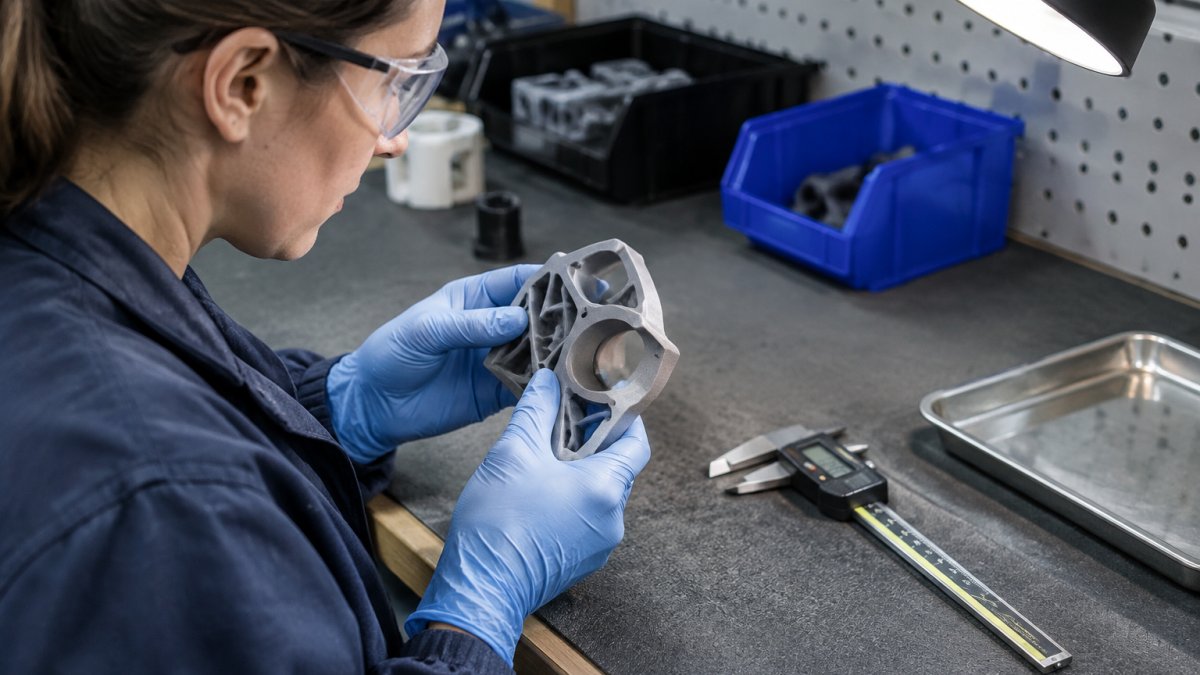
Match the method to the characteristic, not to habit. Calipers and micrometers cover external dimensions and simple feature sizes. Pin gauges and thread gauges verify holes and threads. A coordinate measuring machine (CMM) or an optical comparator is the right call when a customer requires a documented dimensional report or when geometry is too complex for hand tools.
Surface finish is measured with a profilometer when a Ra value is specified, and visual standards or comparator plates handle cosmetic acceptance. For internal porosity and layer bonding, non-destructive options include ultrasonic testing and computed tomography (CT), while destructive methods such as tensile testing, cross-sectioning, and density measurement (Archimedes method) confirm mechanical and internal quality on coupons or sacrificial parts.
Writing Acceptance Criteria That Hold Up
Acceptance criteria should be written, measurable, and tied to the part's function. A cosmetic trade-show piece and a load-bearing bracket do not share the same bar. The practical format is a characteristic, a method, a limit, and a reaction:
- Critical dimension: caliper or CMM; within the drawing tolerance (for example, ±0.005 in on a machined interface); reject and quarantine if out.
- Wall thickness: ultrasonic thickness gauge or CT; not less than the design minimum; re-slice or scrap if under.
- Porosity: CT or cross-section; no void greater than the agreed threshold in a load path; escalate to engineering if exceeded.
- Surface finish: profilometer or visual comparator; Ra at or below the specified value on sealing faces; rework or reject if over.
- Layer bonding: tensile or flexural coupon test per lot; at or above the material datasheet minimum; hold the lot if under.
- Cosmetic defects: visual against a boundary sample; no cracks, delamination, or discoloration on A-surfaces; rework or downgrade if present.
Write the reaction for every criterion before the first print. "Reject" without a disposition path just moves the problem to the shelf.
Watch out: acceptance criteria copied from a metal-machining drawing often specify tolerances and surface finishes that polymer additive processes cannot hit without post-machining, so confirm the process can meet the callout before you promise it.
Common defects to screen for:
Upload your STL file for an instant quote →
- Porosity in the walls or between layers
- Layer shifts and visible banding
- Dimensional drift outside tolerance
- Poor surface finish on critical faces
- Weak layer bonding at load points
When a part fails, our diagnostic guide to why 3D printed prototypes fail helps trace the cause back to the process.
How to Measure 3D Printing Dimensional Accuracy and Set Tolerances
Start with the measurement method, then set the tolerance. Not the other way around.
Calipers handle most external dimensions. Micrometers suit tight features. A coordinate measuring machine is the right tool when a customer demands a documented dimensional report.
Set tolerances from the process capability, not from wishful thinking. Layer height, extrusion width, and print speed all move the achievable window. If you need tighter tolerances than the process delivers, change the process or plan post-processing. For a deeper walkthrough, read achieving tight tolerances in 3D printing.
Risk-Based Sampling, Validation, and Statistical Process Control
You cannot inspect every part on a long run. So sample by risk, and write the plan down before production starts.
Building a Risk-Based Inspection Plan
Classify each characteristic by severity and likelihood. Safety-relevant geometry, mating interfaces, and tight tolerances are high risk; cosmetic features on hidden faces are low risk. Then assign an inspection level:
- First-article inspection (FAI): the first conforming part from a new machine, material lot, or program is fully inspected against every drawing characteristic, with results recorded on an FAI report. Production does not release until FAI passes.
- High-risk features: 100% inspection, or a tightened sample (for example, every fifth part) with a documented reaction plan.
- Low-risk features: periodic sampling at a defined frequency (per shift, per lot, or per build), with results logged and trended.
- Escalation: any nonconformance triggers containment of the affected lot, root-cause analysis, and a return to FAI-level inspection until the process is re-qualified.
A common pattern is to tie sample size to lot size and criticality rather than to a fixed number, so a 50-part lot and a 5,000-part lot do not get the same scrutiny.
Process Qualification and Validation
Validation means proving the process produces conforming parts repeatably, not that one good part came off the bed. Qualify the machine and material combination by running a defined build across the build envelope, measuring the critical characteristics, and demonstrating that results stay within tolerance across positions, operators, and runs. Re-qualify after a machine move, a major repair, a material supplier change, or a slicer profile change that affects the critical characteristics. A process that only passes when someone babysits it is not validated.
Statistical Process Control in Practice
SPC means tracking measurements over time and reacting when they drift, before parts go out of spec. Record the measured value for each sampled characteristic, plot it on a control chart (X-bar and R charts for variable data, p-charts for pass/fail attributes), and set control limits from the process's own variation rather than from the drawing tolerance.
Watch out: control limits set from a short, favorable run will flag normal variation as a problem, so establish baseline capability from enough subgroups to represent the process before you trust the chart.
Traceability and Documentation That Survive an Audit
An auditor does not want to hear that the part is good. They want to see the record that proves it.
Keep these together for every job:
- Material lot and supplier records
- Machine ID and calibration history
- Slicer settings and file revision
- Inspection measurements and pass/fail results
- Operator name and date
If a customer questions a batch six months later, that file is your answer. Build the habit early, because reconstructing records after the fact never works.
Upload Your STL for a Quote and a Quality Plan
Quality control starts before the first layer, and it starts with a clean file.
At Alex 3D Print Us LLC, we run Bambu Lab multi-color printing, xTool UV and MOPA laser engraving, and turnkey engineering support for projects of any complexity. You get an instant quote from your STL file.
Upload your STL file for an instant quote and put a documented quality process behind your next build.
Frequently Asked Questions
What quality standards apply to 3D printing?
The core set comes from ISO and ASTM, now jointly published as ISO/ASTM 52900 for terminology and 52901 for purchasing guidelines, plus process-specific documents like 52920 for polymer powder bed fusion and 52941 for metal laser systems. Which ones bind you depends on your process, material, and customer industry. Aerospace and medical buyers layer on their own requirements. For most commercial work, a documented internal quality plan built on ISO/ASTM language satisfies customers faster than chasing every certificate.
How do you inspect the quality of a 3D printed part?
Start with a visual check for layer shifting, stringing, under-extrusion, and warping. Then measure critical dimensions with calipers or a coordinate measuring machine against your drawing tolerances. Weigh the part against the slicer's predicted mass to catch internal voids. For functional parts, add porosity checks or mechanical testing. Record every result on a 3D printed part inspection sheet tied to the build and material lot, so a failed batch can be traced back to its parameters.
What is the difference between quality assurance and quality control in 3D printing?
Quality assurance is the system you build before printing: approved materials, calibrated machines, qualified operators, documented process parameters, and a defined inspection plan. Quality control is the execution on each job: checking the file, monitoring the build, measuring the finished component, and signing off. QA prevents defects; QC catches the ones that slip through. A shop with strong QC but no QA repeats the same failures, because nothing upstream changes.
How can you ensure consistent quality in 3D printing?
Lock your variables. Keep a fixed slicer profile per material and machine, calibrate flow and first-layer height on a schedule, store filament and powder per the manufacturer's spec, and log every parameter with the build. Run validation builds after any hardware change and track key dimensions on a control chart so drift shows up before a customer does. Consistency comes from repeatability of the process, not from inspecting harder at the end.
The gap between a part that ships and one that gets scrapped usually comes down to documentation, not hardware. If your current process relies on eyeballing parts and hoping, the fix is a written checklist and a record for every job. Get started with Alex 3D Print Us LLC and turn your next prototype run into a documented, repeatable process.
